
Microcontroller Kits
Programmer and Target 89s51![]()
Simple Mikrokontroller 89s51 Trainer
Standart
Mikrokontroller 89s51 Trainer![]()
Super Mikrokontroller Trainer 89s51
All Item Include
3.1. Timer/ Counter Mode 0 : 13 bit Counter
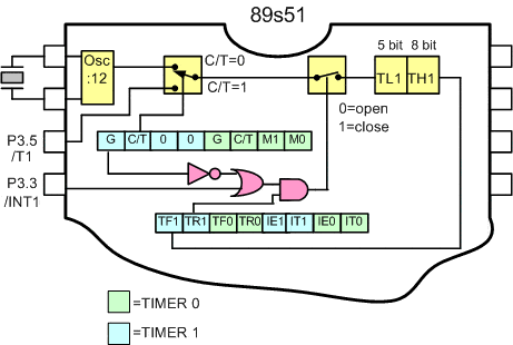
Putting either Timer into Mode 0 makes it look like an 8048 Timer, which is an 8-bit Counter with a divide-by-32 prescaler. Figure 7 shows the Mode 0 operation as it applies to Timer 1. In this mode, the Timer register is configured as a 13-bit register. As the count rolls over from all 1s to all 0s, it sets the Timer interrupt flag TF1. The counted input is enabled to the Timer when TR1 = 1 and either GATE = 0 or INT1 = 1. (Setting GATE = 1 allows the Timer to be controlled by external input INT1, to facilitate pulse width measurements). TR1 is a control bit in the Special Function Register TCON (Figure 8). GATE is in TMOD.

Figure 3.1. Timer/Counter Mode 0: 13-Bit Counter
The 13-bit register consists of all 8 bits of TH1 and the lower 5 bits of TL1. The upper 3 bits of TL1 are indeterminate and should be ignored. Setting the run flag (TR1) does not clear the registers. Mode 0 operation is the same for the Timer 0 as for Timer 1. Substitute TR0, TF0, and INT0 for the corresponding Timer 1
signals in Figure 7. There are two different GATE bits, one for Timer 1 (TMOD.7) and one for Timer 0 (TMOD.3).
3.1.1 Generate pulse by using Timer 1 in mode 0
By using Timer function, we can design a pulse generator and outputs data to port. as you see on figure 3.3.1., with frequency 1 Hz
Step 1st
Build the circuit as shown in figure 3.1.1. As you seen on figure 3.1.1. P0.0 is connected to LED. Remember, that all we want to do with this lesson is generate a pulse with frequency 1 Hz
Step 2nd
In this step, you must tipe the assembly program to make your Timer get action, we assume that you have already known the editor, we used MIDE-51 to edit the program. ( Download File : exp311.zip )
Figure 3.1.1. A pulse generator from timer function
Figure 3.1.2. Pulse Periode 1 second
This program initialized counter/timer 1 to be a timer operating in mode 0, that is a 13 bit timer. When the timer overflows, the hardware sets the flag TF1. The program spends most of its time checking whether the timer overflow flag TF0 is set. Note that in this mode, with a 12 MHz crystal frequency, the timer overflows every 8192 microseconds.
In this experiment, to generate interruption every 1000 micro second, then :
8192 – 5000 = 3192d or 0C78h
Interruption will come out every 5000 x 1 microsecond = 0,005 second.
R0 is implemented as a software counter, Register R0 is incremented every Timer 0 overflows. If Register R7 detected with value 100 then port P0.0 will output data with Ton = 0,005 x 100 second = 0,5 second.
Org 0hStart: Setb P0.0 ;P0.0 = 1 call Delay ;call delay time Clr P0.0 ;P0.0 = 0 Sjmp Start ;Looping Forever;Delay: Mov R0,#0 ;R0 = 0 Mov TMOD,#00000000b ;mode 1, Timer 1Load: Mov TH1, #00Ch ;TH1 = D8h Mov TL1, #078h ; TL1 = F0h Setb TR1 ; TR1 = 1, Start Running OFlow: JNB TF1, OFlow ; jump to OFlow if TF1 =0 Inc R0 ; R0 = R0+1 CJNE R0,#100,Load; Ret; End
Step 3rd
Safe your assembly program above, and name it with timer1.asm (for example) Compile the program that you have been save by using MIDE-51, see the software instruction.
Step 4th
Download your hex file ( timer1.hex ) into the microcontroller by using Microcontroller ATMEL ISP software, see the instruction.After download this hex file you’ll see the action of Timer( of course if your cable connection and your program are corrected ).
Comments, questions and discussion about this topic