
Microcontroller Kits
Programmer and Target 89s51![]()
Simple Mikrokontroller 89s51 Trainer
Standart
Mikrokontroller 89s51 Trainer![]()
Super Mikrokontroller Trainer 89s51
All Item Include
BACKNEXT
3.4. Timer/ Counter Mode 3 : Two 8 bit counter
Timer 1 in Mode 3 simply holds its count. The effect is the same as setting TR1=0.
Figure 3.4. 1. Timer/ Counter 1 mode 3
Timer 0 in Mode 3 establishes TL0 and TH0 as two separate counters. The logic for Mode 3 on Timer 0 is shown in Figure 10. TL0 uses the Timer 0 control bits: C/T, GATE, TR0, INT0, and TF0. TH0 is locked into a timer function (counting machine cycles) and takes over the use of TR1 and TF1 from Timer 1. Thus, TH0 now controls the “Timer 1” interrupt.
Mode 3 is provided for applications requiring an extra 8-bit timer on the counter. With Timer 0 in Mode 3, an 80C51 can look like it has three Timer/Counters. When Timer 0 is in Mode 3, Timer 1 can be turned on and off by switching it out of and into its own Mode 3, or can still be used by the serial port as a baud rate generator, or in fact, in any application not requiring an interrupt.
3.4.1. Timer/ Counter acts as Counter Mode 3 with output LED
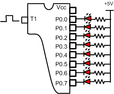
A simple way to detect wheater the counter counting or not is by using 8 LED as output of P0.0 trough P0.7.

Figure 3.4.1. Get data counter out to LED
Step 1st
Build the circuit as shown in figure 3.4.1. As you seen on figure 3.4.1. P0.0 trough P0.7 is connected to LED. Remember, that all we want to do with this lesson is count the pulse and display to LED
Step 2nd
In this step, you must tipe the assembly program to make your Timer get action, we assume that you have already known the editor, we used MIDE-51 to edit the program. ( Download File : exp341.zip )
       org 0h
Start: Mov TMOD,#01110000b ; mode 3 counter 8 bit timer 1       Setb TR1            ; TR1 = 1, start countingGet:   Mov A, TL1          ; A = TL1
CPL A        Mov P1, A           ; P1 = A       Sjmp Get            ; Looping Forever       End
Step 3rd
Safe your assembly program above, and name it with timer3.asm (for example) Compile the program that you have been save by using MIDE-51, see the software instruction.
Step 4th
Download your hex file ( timer3.hex ) into the microcontroller by using Microcontroller ATMEL ISP software, see the instruction.After download this hex file you’ll see the action of Timer( of course if your cable connection and your program are corrected ).
Comments, questions and discussion about this topic
BACKNEXT