
Pelatihan Dasar Mikrokontroller
14-15 April 2007
Surabaya
Rp. 300.000
Microcontroller Kits
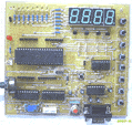
Programmer and Target 89s51
Rp.100.000
(USD $10)
Simple Mikrokontroller 89s51 Trainer
Rp, 350.000
(USD $35)
Standart
Mikrokontroller 89s51 Trainer
Rp. 650.000
(USD $65)
Super Mikrokontroller Trainer 89s51
Rp.1.250.000
(USD $125)
3. Timer/ Counter
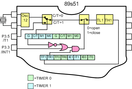
The MCS-51 has two 16 bit Timer/ Counter register. Timer 0 and Timer 1. Both can be configured to operate either as timers or event counters ( see figure 3.1. ).
In the Timer function, the register is incremented every mechine cycle.

Figure 3.1. Diagram block Timer/ Counter Operation
As shown in figure 3.1., microcontroller can be used as timer or counter as you need. The question is, what you have to do, so the microcontroller will act as timer or counter. See left and right swicht on diagram blog. Microcontroller will act as timer when swicht position on upper and microcontroller will act as counter when swicht position on lower by controlling C/T bit on TMOD register. The right swicht position is depent on BIT GATE ( Register TMOD ), TR1 ( Register TCON ) dan INT1.
Timer/ Counter Mode Control ( TMOD ) Register
|
TIMER 1 |
TIMER 0 |
||||||
|
GATE |
C/T |
M1 |
M0 |
GATE |
C/T |
M1 |
M0 |
|
GATE |
Gating control when set. Timer/ Counter X is enabled only while INTx pin is high and TRx control pin is set |
|
C/T |
Timer or Counter Selector cleared for Timer operation (input from internal system clock) and set for counter operation (input from Tx input pin) |
|
M1 |
M0 |
Operating |
| 8048 Timer, TLx serves as 5 bit prescaler | ||
|
16 bit Timer/Counter THx and TLx are cascaded, there is no prescaler |
||
|
8 bit auto reaload Timer/ Counter THx holds a value which is tobe reloaded into TLx each time it overflows |
||
| (Timer 0) TL0 is an 8 bit Timer/ Counter controlled by the standard timer 0 control bits (Timer 1) Timer/ Counter 1 stopped |
Timer/ Counter Control ( TCON ) Register
|
MSB |
LSB |
||||||
|
TF1 |
TR1 |
TF0 |
TR0 |
IE1 |
IT1 |
IE0 |
IT0 |
|
BIT |
SYMBOL |
FUNCTION |
|
TCON.7 |
TF1 |
Timer 1 overflow flag. Set by hardware on Timer/Counter overflow. Cleared by hardware when processor vector to interrupt routine, or clearing the bit in software. |
|
TCON.6 |
TR1 |
Timer 1 Run control bit . Set/ cleared by software to turn Timer/ Counter on/off |
|
TCON.5 |
TF0 |
Timer 0 overflow flag. Set by hardware on Timer/Counter overflow. Cleared by hardware when processor vector to interrupt routine, or clearing the bit in software. |
|
TCON.4 |
TR0 |
Timer 1 Run control bit . Set/ cleared by software to turn Timer/ Counter on/off |
|
TCON.3 |
IE1 |
Interrupt 1 Edge flag. Set by hardware when external interrupt edge detected. Cleared when interrupt processed. |
|
TCON.2 |
IT1 |
Interrupt 1 type control bit. Set/ cleared by software to specefy falling edge/ low level trigerred external interupts |
|
TCON.1 |
IE0 |
Interrupt 0 Edge flag. Set by hardware when external interrupt edge detected. Cleared when interrupt processed. |
|
TCON.0 |
IT0 |
Interrupt 0 type control bit. Set/ cleared by software to specefy falling edge/ low level trigerred external interupts |
Comments, questions and discussion about this topic
Programmer
ISP 89s
Free Software
a. Edsim 51
b. MIDE-51
c. ATMEL ISP
Lesson 1:
Architecture
1.1.Memory
1.2.SFR
1.3.Addressing
1.4.Instruction Set
1.5.Assignment
Lesson 2:
Input Output
2.1.LED
2.2.Swicht
2.3.7 Segmen
2.4.LCD Character
2.5.ADC
2.6.DAC
2.7.Motor Stepper
2.8.Keypad
2.9.Assignment
Lesson 3:
Timer Counter
3.1.Basic
3.2.Mode 0
3.3.Mode 1
3.4.Mode 2
3.5.Mode 3
3.5.Assignment
Lesson 4:
Serial Comm.
4.1.Basic
4.2.LED
4.3.Rotate LED
4.2 ADC
4.3.LCD
4.4.Assignment
Lesson 5:
Interuption
5.1.Basic
5.2.Timer
5.2.External
5.3.Assignment