Basic PWM
One of the easiest ways of generating an analog voltage from a digital value is by pulse-width modulation ( PWM ). I PWM a high frequency square wave is generated as a digital output. For example, a port bit continuously swiched on and off at a reltive high frequency. The signal is fed to a low pass filter. The voltage at the otuput of filter is equal to ther Roo Mean Squeare ( RMS ) of the squeare wave signal. The RMS of the square wave signal may then be varied by changing the duty cycle of the signal. A cycle is initiated by a low to high transition of the signal and terminates at the next such transition. During one cycle if the time the signal stays high is equal to the time the signal stays low, then the duty cycle is said to be 50 percent.
Figure 1. Duty Cycle 30 %
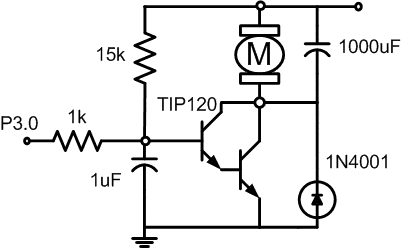
The following circuit shows a DAC constructed with PWM. The Program controls the speed of a DC motor by pulse widht modulation ( PWM ). Bit P3.0 Drives a switching transistor as shown in the circuit diagram. Motor is swiched on for a period of time, and then off. The fraction of time the motor is on is call the duty cycle.

Figure 2. Pulse widht modulation to Control Motor Speed
This program uses a byte to store the time the motor is on, that is the number of cycles out of 256 cycles while the motor is on. a value of 10 means that the motor is on 10 cycles and off 246 cycles.The duty cycle value is stored in the internal register labeled dCycle. The complement of the duty cycle is similarly stored in register labeled dCycleC. ( Download File : motor.zip )
dCycle   equ 30hdCycleC  equ 31hcount    equ 32hAnalog0  equ 33hAnalog1  equ 34hPWM      bit P3.0Channel  bit P3.1PortADC  equ P0DCLB     equ 000hDCUB     equ 0F0hMotorCondition bit 20h;         org 0h         ljmp start         org 0bh         ljmp Timer_Interrupt0start:   call Init_Interrupt_Timer0         clr PWM ; Turn off motor;==================; Main Routine;==================Forever: call ADC         call Update         sjmp Forever;;======================;Subrutine Timer Interruption;======================Timer_Interrupt0:         JB MotorCondition,MotoroFF         Setb PWM         Mov TH0,dCycle         Setb MotorCondition         reti ;Motoroff:clr PWM         mov TH0,dcycleC         clr MotorCondition          reti ;;=========================;Subrutine Initialize Timer Interrupt;timer 0 as counter 8 bit mode 2;========================Init_interrupt_Timer0:         mov TH0,#dCycle         Mov TMOD,#00000010b ;         setb ET0 ; Enable Timer 0 Interrupt         Setb EA ; Master Interrupt Enable          setb TR0 ; start rock and roll timer 0         Setb MotorCondition         mov count,#50         mov dCycle,#0         mov dCycleC,#0FFh         ret
;;========================;Subrutine Update - Update duty cycle;=========================Update:  djnz count,upDone         mov A,analog1; reference voltage         mov b,analog0; tachometer voltage         clr c         subb a,b         jnz update1         retUpdate1: jc decrease         call higherDC         retDecrease:         call lowerDCUpDone:          ret;;====================;Subrutine lowerDC ;====================LowerDC: mov a,dCycle         cjne a,#DCLB,DecDC         ret         DecDC: dec dCycle         inc dCycleC         ret;;===================;Subrutine HigherDC ;===================HigherDC:         mov a,dCycle         cjne a,#DCUB,IncDC         ret         IncDC: Inc dCycle         dec dCycleC         ret;;=============;Subrutine ADC ;=============ADC: Clr channel ; Pick channel X0 from multiplexer 4051     mov Analog0,PortADC     Setb channel ;Pick channel X1 from multiplexer 4051     mov Analog1,PortADC     ret;      end