2.1.4. Running LED ( Get the idea by your self )
Do it, same lesson as 2.a.3 by changing the instruction mov P0,#xxxxxxxxb
with Setb P0.x or Clr P0.x
2.1.5. Running LED ( Get the idea by your self )
Save your space of assembly program by using RR or RL instruction, see Lesson1 for complete set instruction.
2.1.6. Running LED ( Get the idea by your self )
Try another set instruction assembly to run your LED right and left by using RRC and RLC, feel the diference.
2.2. SWICHT
2.2.1. Turn on LED when you’re push the button
A simple way, how to demonstrate input data is by using swicht push button, of course this swicht is mechanically operated. When you are pushing the swicht then the port will get a low logic and high logic in vice reversa.
Step 1st
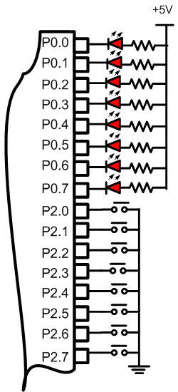
Build the circuit as shown in figure 2.2.1. As you seen on figure 2.2.1. P2.0 trough P2.7 is connected to swicht push button each and LED’s Katode is connected to P0.0 trough P0.7. Remember, that all we want to do with this lesson is make a LED on when, the button connected to P2.0 or P2.1. pushed

Figure 2.2.1. Diagram Skematik Input Data
Step 2nd
In this step, you must tipe the assembly program to make your LED on when you push the swicht, we assume that you have already known the editor, we used MIDE-51 to edit the program.
       org 0h
start: mov A,P2  ; get the data from swicht and save to Acc.       mov P0,A  ; send the data in Acc to P0        sjmp start
end
Step 3rd
Safe your assembly program above, and name it with SW1.asm (for example) Compile the program that you have been save by using MIDE-51, see the software instruction.
Step 4th
Download your hex file ( SW1.hex ) into the microcontroller by using Microcontroller ATMEL ISP software, see the instruction.After download this hex file you’ll see the action of the LED ( of course if your cable connection and your program are corrected ).