
Microcontroller Kits
Programmer and Target 89s51![]()
Simple Mikrokontroller 89s51 Trainer
Standart
Mikrokontroller 89s51 Trainer![]()
Super Mikrokontroller Trainer 89s51
All Item Include
2.3. 7 Segment
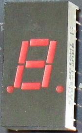
The 7 segment display is found in many displays such as microwaves or fancy toaster ovens and occasionally in non cooking devices. It is just 7 LEDs that have been combined into one case to make a convenient device for displaying numbers and some letters. The display is shown on the left. The pinout of the display is on the right.

Figure 2.3. 7 Segmen
2.3.1. Writing a character to single 7 Segmen
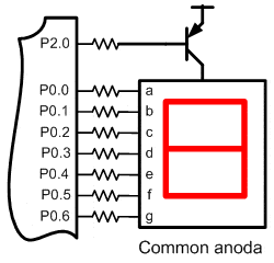
This version is a common anode version. That means that the positive leg of each LED is connected to a common point. Each LED has a negative leg that is connected to one of the pins of the device. To make it work you need to connect pin common to 5 volts trough driver transistor. Then to make each segment light up, connect the ground pin for that led to ground. A resistor is required to limit the current. Rather than using a resistor from each LED to ground, you can just use one resistor from Vcc to pin 3 to limit the current.

Figure 2.3.1. Driving 7 Segmen common anoda
Step 1st
Build the circuit as shown in figure 2.3.1. As you seen on figure 2.3.1. P2.0 is connected to driver transistor, and each pin of 7 segmen is connected to P0.0 trough P0.6. Remember, that all we want to do with this lesson is write a number 1 to 7 segmen.
Step 2nd
In this step, you must tipe the assembly program to make your 7 segmen shown a number on 7 segmen, we assume that you have already known the editor, we used MIDE-51 to edit the program.
       org 0h
start: mov P2,#11111001b; send high logic to a and b segmen       clr P0.0         ; send current to 7 segment       sjmp start       ; jump forever       end
Step 3rd
Safe your assembly program above, and name it with 7seg1.asm (for example) Compile the program that you have been save by using MIDE-51, see the software instruction.
Step 4th
Download your hex file ( 7seg1.hex ) into the microcontroller by using Microcontroller ATMEL ISP software, see the instruction.After download this hex file you’ll see the action of the 7 segmen( of course if your cable connection and your program are corrected ).
Comments, questions and discussion about this topic