
Pelatihan Dasar Mikrokontroller
14-15 April 2007
Surabaya
Rp. 300.000
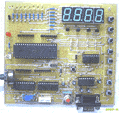
Microcontroller Kits
Programmer and Target 89s51
Rp.100.000
(USD $10)
Simple Mikrokontroller 89s51 Trainer
Rp, 350.000
(USD $35)
Standart
Mikrokontroller 89s51 Trainer
Rp. 650.000
(USD $65)
Super Mikrokontroller Trainer 89s51
Rp.1.250.000
(USD $125)
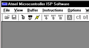
Atmel Microcontroller ISP Software
The Atmel Microcontroller ISP Software is the primary means for performing in-system programming (ISP) for the Atmel devices. It provides an intuitive interface for in-system programming that can be run from your personal computer. The Atmel ISP Software has a comprehensive set of features that allows you to view, program, and erase data from an Atmel ISP device.

Figure 1 – Atmel Microcontroller ISP Software
The Atmel Microcontroller ISP Software also allows you to load hex files containing the code you want to add to the device. Using the software, you can manipulate this code, verify it against the existing code on the device, and program the code onto the device.
You will notice that most of the toolbar buttons and menu options are disabled. This is because a device has not been selected. To select a device, do the following:
1. Make sure the board is connected to the LPT port of your computer with the Atmel ISP cable and that the board is turned on.
2. Select the LPT port that the board is connected to by selecting Select Port from the Options menu (You could also press the select port toolbar button).
Figure 2 – Port Select Dialog
3. You can then select a device by choosing Select Device from the Options menu or by clicking on the toolbar. You should see a dialog box similar to the one in Figure 3.
Figure 3 – Device Select Dialog
4. Select the device that you are trying to program from the tree control by clicking on the desired device.
5. Next select whether you want to read and write from the device in page mode (read/write a page at a time) or in byte mode (read/write byte by byte).
6. Enter the external clock frequency (MHz) provided to the device in the text box.
7. Select OK.
Once you finished selecting a device you will see one or two windows appear depending on whether or not the device has internal data memory. The window(s) will look like Figure 4. Each window signifies a buffer. There are two types of buffers, a code buffer and a data buffer. The code buffer corresponds with the in-system programmable flash memory of the chip and the data buffer corresponds with the chip’s internal data memory.
Figure 4 – Buffer Window
Comments, questions and discussion about this topic
Programmer
ISP 89s
Free Software
a. Edsim 51
b. MIDE-51
c. ATMEL ISP
Lesson 1:
Architecture
1.1.Memory
1.2.SFR
1.3.Addressing
1.4.Instruction Set
1.5.Assignment
Lesson 2:
Input Output
2.1.LED
2.2.Swicht
2.3.7 Segmen
2.4.LCD Character
2.5.ADC
2.6.DAC
2.7.Motor Stepper
2.8.Keypad
2.9.Assignment
Lesson 3:
Timer Counter
3.1.Basic
3.2.Mode 0
3.3.Mode 1
3.4.Mode 2
3.5.Mode 3
3.5.Assignment
Lesson 4:
Serial Comm.
4.1.Basic
4.2.LED
4.3.Rotate LED
4.2 ADC
4.3.LCD
4.4.Assignment
Lesson 5:
Interuption
5.1.Basic
5.2.Timer
5.2.External
5.3.Assignment