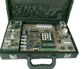

Microcontroller Kits
Programmer and Target 89s51![]()
Simple Mikrokontroller 89s51 Trainer
Standart
Mikrokontroller 89s51 Trainer![]()
Super Mikrokontroller Trainer 89s51
All Item Include
5.2.2. Digital Clock ( :SS)
The next example implements interrupt Timer 0 as digital clock, in this example will display second at 8 x7 segmen module ( fist and second 7 segmen ).
Step 1st
Build the circuit as shown in figure 5.2.1. As you seen on figure 5.2.1. P0 and P2 is connected to 8 x 7 Segmen. Remember, that all we want to do with this lesson displays digital clock as second part only
Figure 5.2.2. Digital clock with timer 0 interrupt
Step 2nd
In this step, you must tipe the assembly program to make your Timer get action, we assume that you have already known the editor, we used MIDE-51 to edit the program. ( Download File : exp522.zip )
Note that in this mode, with a 12 MHz crystal frequency, the timer overflows every 65,536 microseconds.
In this experiment, to generate interruption every 1000 micro second, then :
65536 – 50000 = 15536 d or 3CB0h ( TL0 = B0h dan TH0 = 3Ch )
Interruption will come out every 50000 x 1 microsecond = 0.05 second.
R0 is implemented as a software counter, Register R0 is incremented every Timer 0 overflows. If Register R7 detected with value 20 then data will be incremented
second     equ 30h
secondTens equ 31h
secondOnes equ 32h
counter20  equ 33h

Org 0h
sjmp Start
Org 0bh
Ljmp Interrupt_Timer0

Start: mov P3,#11111111b
mov second,#0
call InitTimer

Forever:
call ClockDisplay
sjmp Forever ;

Interrupt_Timer0:
mov tl0,#0b0h
mov th0,#03ch
djnz Counter20, EndInterrupt
mov Counter20,#20
call DoClock
EndInterrupt:
reti
;
DoClock:
inc second
mov A,second
cjne A,#60,Update
mov second,#0
Update:mov A,second
mov B,#10
DIV AB
mov SecondTens,A
mov SecondOnes,B
ret

ClockDisplay:
Setb P2.7
Mov DPTR,#Decoder7Segmen
mov A,secondOnes
Movc A,@A+DPTR
Mov P0,A
Clr P2.7
call delay

Setb P2.7
Mov DPTR,#Decoder7Segmen
mov A,secondTens
Movc A,@A+DPTR
Mov P0,A
Clr P2.6
call delay
ret

InitTimer:
mov TMOD,#00000001b
mov tl0,#0b0h
mov th0,#03ch
setb ET0           ;Enable Timer 0 Interrupt
setb EA            ;Master Interrupt Enable
setb TR0           ;Clock start running
ret

;=============================================
;subroutine delay created to rise delay time
;=============================================
delay: mov R1,#255
del1:  mov R2,#255
del2:  djnz R2,del2
djnz R1,del1
ret
;========================================
; L O O K U P T A B L E
; Decode to Seven Segmen -> g f e d c b a
;========================================
Decoder7Segmen:
DB 11000000b,11111001b,10100100b,10110000b,10011001b
DB 10010010b,10000010b,11111000b,10000000b,10010000b

End
Step 3rd
Safe your assembly program above, and name it with int2.asm (for example) Compile the program that you have been save by using MIDE-51, see the software instruction.
Step 4th
Download your hex file ( int2.hex ) into the microcontroller by using Microcontroller ATMEL ISP software, see the instruction.After download this hex file you’ll see the action of Interruption( of course if your cable connection and your program are corrected ).
Comments, questions and discussion about this topic