
Pelatihan Dasar Mikrokontroller
14-15 April 2007
Surabaya
Rp. 300.000
Microcontroller Kits
Programmer and Target 89s51
Rp.100.000
(USD $10)
Simple Mikrokontroller 89s51 Trainer
Rp, 350.000
(USD $35)
Standart
Mikrokontroller 89s51 Trainer
Rp. 650.000
(USD $65)
Super Mikrokontroller Trainer 89s51
Rp.1.250.000
(USD $125)
Connecting Microcontrollers to Nokia 3310
embededtronic.com
How to connect microcontrollers to your Nokia 3310
Most Nokia phones have F-Bus and M-Bus connections that can be used to connect a phone to a PC or in our case a microcontroller. The connection can be used for controlling just about all functions of the phone, as well as uploading new firmware etc. This bus will allow us to send and receive SMS messages. Want to turn your air-conditioner on remotely?
The very popular Nokia 3310/3315 has the F/M Bus connection under the battery holder. This is a bit of a pain to get to and requires a special cable to make the connection. The left picture above shows the 4 gold pads used for the F and M Bus. The right picture shows the F-Bus cable connected to my Nokia 3310.
Nokia 3310, 3315, 3330, 3350, 3390, 3410, 5510 cell phones common pinout
| Pin Number | Pin Name | Direction |
| MBUS | <–> | |
| GND | — | |
| RX | <– | |
| TX | –> |
Nokia download cables are available from most mobile phone shops and some electronics stores. I brought my cable from Dick Smith electronics in Australia. The cost of the Nokia 3310 download cable is around $30AUD and is an excellent investment to get the most out of your phone. You can use PC software like Logomanager and Oxygen Phone Manager (See links below) to upload ringtones, graphics, phone numbers etc. No more paying for those cool ringtones, just download them off the internet or record your own! I have even designed a ringtone doorbell, just what every house needs! The cable contains electronics to level convert 3V signals to RS232 type signals. There are also M and F bus switching in most cables.
Some pages have schematics for making your own cable, however I think it’s easier to buy one, as the phone connectors are very hard to come by.
The differences of M-Bus and F-Bus
M-Bus is a one pin bi-directional bus for both transmitting and receiving data from the phone. It is slow (9600bps) and only half-duplex. Only two pins on the phone are used. One ground and one data. M-Bus runs at 9600bps, 8 data bits, odd parity, one stop bit. The data terminal ready (DTR) pin must be cleared with the request to send (RTS). This powers the electronics in the cable and I think it sets it for M-Bus operation.
F-Bus is the later high-speed full-duplex bus. It uses one pin for transmitting data and one pin for receiving data plus the ground pin. Very much like a standard serial port. It is fast 115,200bps, 8 data bits, no parity, one stop bit. For F-Bus the data terminal ready (DTR) pin must be set and the request to send (RTS) pin cleared.
The F-Bus Protocol and Commands
The F-Bus is bi-directional serial type bus running at 115,200bps, 8 data bits. The serial cable contains electronics for level conversion and therefore requires power. The first thing to do is supply power to the cable electronics and this is done by setting the DTR (Data Terminal Ready) pin and clearing the RTS (Request to Send) pin.
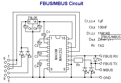
Added 29-Dec-2003 – For all you microcontroller DIYer’s out there, connect the DTR pin to a +3 to 12 Volt supply and RTS to a -3 to -12Volt supply. The easy way to achieve this is by using a Max232 or similar transceiver for the RS232 TX and RX pins and then connecting the DTR pin on the serial cable to the V+ pin on the Max232. Do the same for the RTS, however connect it to the V- pin on the Max232. The V+ and V- pins are derived from internal charge pumps that double the input voltage. ie. for a 5V Max232, the V+ will +10V and the V- will be -10V. I hope this clears up this issue for most people!
The next step is to synchronize the UART in the phone with your PC or microcontroller. This is done by sending a string of 0x55 or ‘U’ 128 times. Simple! The bus is now ready to be used for sending frames.
The Nokia protocol has a series of commands that allow the user to make calls, send and get SMS messages and lots more. If you have not already go to The Linux Gnokii Project and download the source code. This group has excellent documentation on the commands used with different Nokia phones. This is great work guys! Please do not email me for the Nokia Commands – If you want them download the Linux Gnokii Project Source
Sample frame sent to my Nokia 3310 (showed as a Hex dump)
Byte: 00 01 02 03 04 05 06 07 08 09 10 11 12 13 14 15
Data: 1E 00 0C D1 00 07 00 01 00 03 00 01 60 00 72 D5
This sample frame is used to get the hardware and software version from a Nokia phone. It is a good starting point to test if our implementation of the protocol is working.
Byte 0: All frames sent by cable will start with the character 0x1E first. This is the F-Bus Frame ID. Cable is 0x1E and InfraRed is 0x1C. Byte 1: This is the destination address. When sending data, it’s the phone’s device ID byte. In our case it’s always 00 for the phone.
Byte 2: This is the source address. When sending data, it’s the PC’s device ID byte. In our case it’s always 0x0C (Terminal).
Byte 3: This is the message type or ‘command’. 0xD1 is Get HW & SW version.
Byte 4 & 5: Byte 4 & 5 is the message length. In our case it is 7 bytes long. Byte 4 is the MSB and byte 5 is the LSB. Thanks to Ron Reiter for comfirming this!
Byte 6: The data segment starts here and goes for 7 bytes in our case. As The Nokia is a 16 bit phone and therefore requires an even number of bytes. As ours is odd the last byte will be a padding byte and the message will end at location 13.
The last byte in the data segment (Byte 12 above) is the sequence number. The last 3 bits of this byte increments from 0 to 7 for each frame. This part needs to be sent back to the phone in the acknowledge frame. The other bits I am unsure about what they mean!
Bytes 14 & 15: The second to last byte is always the odd checksum byte and the last byte is the even checksum byte. The checksum is calculated by XORing all the odd bytes and placing the result in the odd Checksum location and then XORing the even bytes and then placing the result in the even byte.
Well that is our first frame for our Nokia Phone. If the phone received it is show reply with the following data
1E 0C 00 7F 00 02 D1 00 CF 71
1E 0C 00 D2 00 26 01 00 00 03 56 20 30 34 2E 34 35 0A 32 31 2D 30 36 2D 30 31 0A 4E 48 4D 2D 35 0A 28 63 29 20 4E 4D
50 2E 00 01 41 3F A4
The first line is an Acknowledge command frame. Notice how the destination and source addresses are now swapped. This is because the Nokia phone is now talking. This message is two bytes long with the two bytes representing the message type received (0xD1) and the sequence number (0x00). The last two bytes are the checksum and should be checked to make sure the data is correct. The 3310 will be waiting for an acknowledge frame after these two frames were sent. If the acknowledge frame is not sent the 3310 will retry sending the data. The 3310 will only send the data 3 times and then gives up.
The second frame from our Nokia 3310 is the data we requested. The message type is 0xD2. This is ‘receive Get HW&SW version’. This 38-byte (0x26) message should show 0x0003 “V ” “firmwaren” “firmware daten” “modeln” “(c)NMP.” The last byte in the data is the sequence number. As with standard F-bus frames, the last two bytes in the frame are checksum bytes.
The received data without f-bus frame
01 00 00 03 56 20 30 34 2E 34 35 0A 32 31 2D 30 36 2D 30 31 0A 4E 48 4D 2D 35 0A 28 63 29 20 4E 4D 50 2E 00 01 41
0003 V 0 4 . 4 5 n 2 1 / 0 6 / 0 1 n N H M – 5 n ( c ) N M P . Sequence no.
All that is required now is to send a acknowledge frame back to the phone to say ‘I got it!’
1E 00 0C 7F 00 02 D2 01 C0 7C
0x7F is the acknowledge frame’s command. We are only required to send a two-byte message so length is set to 0x02. The message contains the acknowledged message type (0xD2) and the sequence no. (0x01). The sequence number is made from the last 3 bits of the sequence number in the previous frame. The checksum needs to be calculated and sent.
Well that’s easy now! We will look at sending SMS messages next, (part two) and look at the AVR hardware for the project in part three, coming soon!!

The circuit is so simple that a printed circuit board is not required. The DB9 (female) connector is soldered directly on the edge of the board. (The five pins of the connector shown in figure above are on the copper side of the board. The board is pushed into the gap between soldering lugs 1…5 and 6…9 of the connector.) Remember to short-circuit pins 1 and 2 of the connector as shown in figure above Circuit board layout for copper-striped board (component side).
The capacitors could be almost any kind according to Maxim, and I used 1 µF 35 V tantalum ones because of their small size. The voltage rating of 16 volts is enough. The two diodes in the circuit are schottky ones to avoid unnecessary voltage drop.
Use an IC socket for MAX232. Please note that in the circuit board layout shown in the figure above the pins 1, 3, 11, and 14 of the IC socket must be cut away.
Please note that this circuit uses the internal pull-up of the MBUS pin of the phone for pulling up the FBUS Rx line. The connection to the MBUS pin is therefore required, even this circuit does not function as an MBUS-adapter. If you are going to use this adapter with a Nokia 3310/5100/6100 series phone, you must connect the FBUS Rx & MBUS to pins 6 and 7, FBUS Tx to pin 8 and GND to 9 in the connector of the phone. See chapter 2 for pin arrangement.
The connection to the phone is the hardest step. The easiest solution is to find an inexpensive headset with all pins connected and cut the connector from it. Check that the connector is openable.
Comments, questions and discussion about this topic