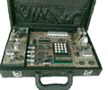

Microcontroller Kits
Programmer and Target 89s51![]()
Simple Mikrokontroller 89s51 Trainer
Standart
Mikrokontroller 89s51 Trainer![]()
Super Mikrokontroller Trainer 89s51
All Item Include
Serial Port Control ( SCON ) Register
| MSB | LSB | ||||||
|
SM0 |
SM1 |
SM2 |
REN |
TB8 |
RB8 |
TI |
RI |
Where SM0, SM1 specify the serial port mode, as follows
|
SM0 |
SM1 |
Mode |
Description |
Baud Rate |
|
Shif Register |
fosc/ 12 | |||
|
8 bit UART |
variable | |||
|
9 bit UART |
fosc/64 fosc/32 | |||
|
9 bit UART |
variable |
Note:
| SM2 |
Enables the multiprocessor communication feature in Modes 2 and 3. In Mode 2 or 3, if SM2 is set to 1, then Rl will not be activated if the received 9th data bit (RB8) is 0. In Mode 1, if SM2=1 then RI will not be activated if a valid stop bit was not received. In Mode 0, SM2 should be 0. |
| REN |
Enables serial reception. Set by software to enable reception. Clear by software to disable reception. |
| TB8 |
The 9th data bit that will be transmitted in Modes 2 and 3. Set or clear by software as desired. |
| RB8 |
In Modes 2 and 3, is the 9th data bit that was received. In Mode 1, it SM2=0, RB8 is the stop bit that was received. In Mode 0, |
| TI |
Transmit interrupt flag. Set by hardware at the end of the 8th bit time in Mode 0, or at the beginning of the stop bit in the other modes, in any serial transmission. Must be cleared by software. |
| RI |
Receive interrupt flag. Set by hardware at the end of the 8th bit time in Mode 0, or halfway through the stop bit time in the other modes, in any serial reception (except see SM2). Must be cleared by software. |
Comments, questions and discussion about this topic